|
A simple and effective boost controller for an external wastegate (or internal, see note at end) can be constructed with simple
hardware store parts. This controller installs between the pressurized manifold and the wastegate. The controller prevents
any pressure from reaching the wastegate untill the desired manifold pressure is reached thus preventing premature wastegate
"cracking open" before the set pressure level is reached. A 1-2psi boost spike occurs when the wastegate opens but
manifold pressure quickly levels off to a constant regulated levell. This is a true manual wastegate controller, not just
a bleed off valve. Sustained boost pressure regulation is not as reliable using a bleed off system and these systems tend
to allow the wastegate to open prematurly. Bleed off valves do not actualy open th wastegatet at a preset level. A bleed off
valve can only temporarily "trick" the wastegate into seeing less pressure than actualy exist. Eventualy the slight
amount of air that does get through a bleed controller will trip the wastegate open.
OPERATION: Pressure enters from the hose barb on the right side of the drawing. A ball bearing is pressed into an airtight
seat formed in the threaded end of the inlet hose barb preventing boost pressure from passing through the controller untill
manifold pressure is sufficient to overcome the preload of the spring and push the bearing off the seat. To increase the boost
level, just add more preload to the spring by adjusting the screw. It may seem that the bearing would serve as a check valve
trapping pressure inside the wastegate once it opens. However, external wastegates are constructed with a poppet valve stem
passing into the pressurized diaphragm chamber (like an intake valve and valve guide). Gas leaks by the valve stem quickly
enough to allow the wastegate to quickly bleed off pressure and close once manifold pressure drops. (or install a small air
bleed between valve and external sealed wastegate).
BOOST CONTROLLER INSTALATION
The controller is really very easy to install. It comes with in-depth installation instructions which I found were just
a little TOO in-depth to follow very eaisly. :)
The following Visual Installation Instructions are ONLY
for 1995-1999 Eagle Talons and Mitsubishi Eclipses.
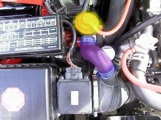
Here you see a view of an engine compartment.
The colors of the various pieces will not match your own.
The yellow red lid with the red hose running out of it is the Blow Off Valve.
The purple tube running south of the BOV is the dump tube.
The Dump Tube is held on by two silver clamps (blue in the picture above).
Unscrew those clamps and pull the dump tube off.
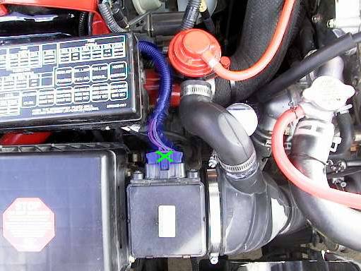
This is what the engine bay looks like with the tube removed.
(Remember, most of your colors will not match the ones in the pictures)
Your next step is to unplug the MAS sensor (the blue harness in the picture).
Unhook the MAS by pressing down on the release (underneath the green
"X") and wiggling the sensor slightly back and forth while pulling.
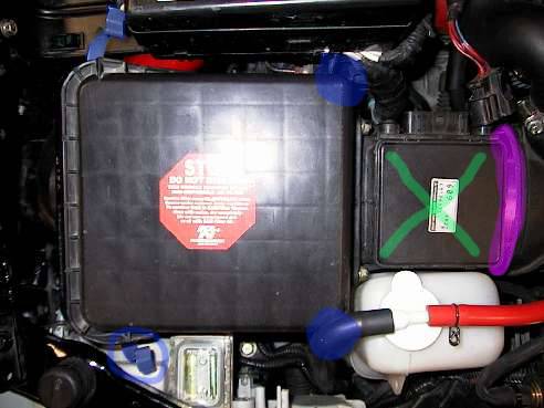
With the harness unplugged, now unclip the four, brass-colored clamps
located at each corner of the airbox (in blue). Also unscrew the large,
silver clamp, which is holding the rest of the airbox in place (in purple).
Wiggle and pull the top of the airbox along
with the MAS (green "X") out of the car.
Pull your coolant resevoir straight up (large white container
half-full of fluid), and stick it somewhere out of the way.
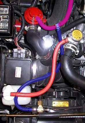
Now with the airbox removed you'll have the same view as in the picture above.
Unhook both of the blue hoses from the Wastegate Solenoid (in red).
Unhook the one blue hose going to the intake pipe and plug the nipple
that is left sticking out of the intake (under the yellow "X")
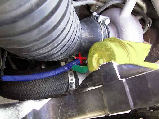
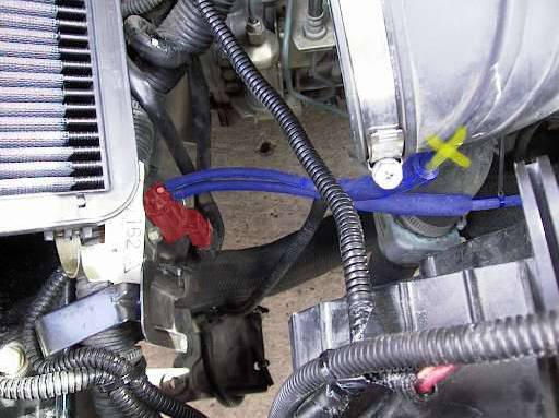
This is a closeup of where the final blue hose is going -- to a "Y" split.
After the "Y", the blue hose continues on to the Turbo Compressor Housing,
and the green hose is attached to the turbo wastegate (yellow in the picture).
Pull the the entire hose, "Y" split and all, out of the car.
Plug the nipple on the Turbo Compressor Housing (red
"X") with the other rubber stopper in your kit.
The green hose (in the picture) on the bottom of the Boost Controller goes to the wastegate nipple (yellow) that you have
just unplugged the stock hose from (purple "X").
Now set your coolant resevoir (white tank) back in place, put the airbox back on, reattach the dump tube, reconnect the
MAS Harness plug, and tighten all neccessary clamps.
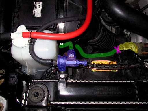
Mount your Manual Boost Controller (blue) along the same lines as seen above (or in any other spot you may find more convienent).
You should be left with one final, currently disconnected
hose coming from the boost Controller.
You will need to cut the stock hose (purple) anywhere you
would like, and tee the Boost controller (blue) into it.
Wrap zip-ties (included in your kit) around all the
hose connections so they stay good and tight.
Now you're done with the installation!!
Time to tune....
Take your car out and see how high your max boost will go.
Be sure to pay very close attention to your aftermarket boost gauge,
(you better have one!!) so you don't over-boost and wreck your engine.
With the stock turbo, you should not run over 15PSI of boost for more than
a few seconds. 15PSI is the max steady boost pressure you should strive for.
Be sure you're not around much traffic while tuning, as you will need to pull-
over frequently to make adjustments. Unscrew the screw to lower boost,
screw it in to raise it. Adjustments are very sensitive, so only
move the screw a rotation or two at a time. Good luck!!
|

