|
Why an EGT gauge?
With an EGT gauge monitoring you're #1 cylinder (belt side cylinder), you can observe and be forewarned of potential leaning-out
problems leading to catastrophic failure due to excessive engine temperatures. When you're engine is running lean (a high
Air-Fuel ratio), the combustion temperatures climb dangerously high. If not corrected it will likely lead to "holing
a piston." This is when the cylinder wall essentially melts (usually at a point, hence the term hole).
Do I need to worry about leaning out?
Unless you are running above stock boost levels (13+ lbs), you don't need to worry about it since the stock fuel pump
can provide enough fuel to keep up and prevention of leaning out.
There is a fair amount of repetitive information with an EGT gauge and A/F mixture gauge. Both will warn of a leaning
condition for example. The difference is that an A/F Gauge shows the instantaneous mixture, not what is actually going on
inside the engine. Honestly if I had to chose between the two, I'd go with the EGT since it shows the actual engine's condition,
the A/F only shows mixture (which is only related to the engine's condition).
Installation Procedures
1. Remove the manifold upper heat shield
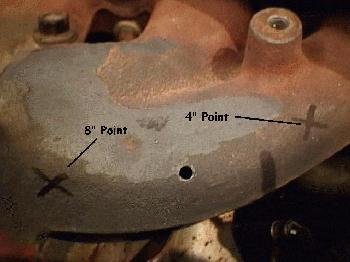
2. The probe needs to be between 4" and 8" from the #1 cylinder (cylinder closest to belts) manifold. So
take the marker and make a point approx. 6" from where the #1 cylinder exhaust path leaves the cylinder.
3. Now mark in you're head where that 6" point is and put back on the heat shield. Now take you're 5/16"
drill bit and drill through the heat shield where you think that 6" point is. Only drill through the shield NOT the manifold...yet.
4. Now take out you're marker again and make a mark through the hole you just drilled onto the manifold. We are doing
this so that the thermocouple probe and exit hole on the heat shield are perfectly lined up. Unlike mine which I did the heat
shield hole last and had to guess...3 holes later I found it!
5. Remove the heat shield
6. Take you're small 5/64" drill bit and start a small hole in the manifold at the point you just marked. It takes
a little effort to get the hole started, but as soon as the drill bit bites it goes pretty easy. When you feel the bit start
biting STOP. We don't want to complete the hole just yet.
7. Start the car...YES, start the car. We want to keep as few chips from our drilling as possible from being eaten
up by the turbo. So starting the engine will do two things: a) blow some pieces of our drilling straight out through the hole
you're making, and b) blow the remaining pieces out through the turbo with it not spinning. At idle there is not boost present.
8. Continue drilling with you're small drill bit till you get all the way through. The puft-puft-puft sound you hear
is the exhaust gases escaping through you're new hole. Now get a slightly larger 1/8" bit and increase the size of the
hole you just made. Now repeat again with the final 3/16" bit. I am suggesting you doing it in steps to minimize the
size of the metal chunks produced. Going from 5/64" to 3/16" in one step would produce some pretty big chunks that
might catch onto something. The final hole will look something like this.
9. Turn off the car. Be careful...it's amazing how quickly the manifold gets hot so don't get burnt!
10. You need to take you're own hose clamp and separate it then feed it into the clamp of the thermocouple. This will
effectively increase the diameter of the thermocouple clamp to accommodate the size of the exhaust manifold. The modified
clamp is seen here.
11. Wrap this clamp around the manifold and place the thermocouple probe into the hole you drilled. Attach the clamp
and tighten. The final assembly is here.
12. Feed the wire through the heat shield and reattach the heat shield. You may have to straighten the probe leads (mine
came with a 90 degree bend) to come straight out through the heat shield. This assembly can be seen here (a little blurry),
along with my 3 guesses at the probe's location in the heat shield. This problem was corrected with step #4.
13. Run the lead through the firewall (were you're boost line runs), and tap it into the gauge. I'll leave the where/how
instruction on the gauge side to you since it's very elementary. I was about 10" short between the thermocouple lead
and the gauge extension wires, so I just used a set of speaker wire and the temperatures were what I expected so I don't think
there is any problem in using the speaker wire. You can order an extension wire when you order you're gauge, but I don't know
what the part numbers/prices are on those.
Expected Temperature Readings (in F)
Idle after warm-up: 900-1000F
Normal constant speed (~3000 RPM): 1350-1400F
Danger: 1650F+
|

